Understanding the Differences Between VRF and Split Systems


When it comes to heating, ventilation, and air conditioning (HVAC), two popular options are Variable Refrigerant Flow (VRF) systems and traditional split systems. While both effectively control indoor climates, they differ significantly in design, functionality, and applications.

What is a Split System?

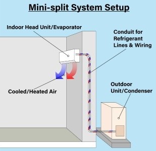
A split system consists of two main components: an indoor unit and an outdoor unit. The outdoor unit houses the compressor and condenser, while the indoor unit contains the evaporator coil. These units are connected by refrigerant lines, allowing for heat exchange.

Key Features of Split Systems:

Simplicity: Split systems are relatively straightforward in design, making installation easier and generally less expensive.

Zoning Limitations: Each indoor unit operates independently, but typically, you can only cool or heat one area at a time per system, limiting zoning capabilities.

Cost-Effectiveness: They are generally more affordable upfront compared to VRF systems, making them a popular choice for smaller homes or individual spaces.

Maintenance: Maintenance is usually more straightforward, with fewer complex components and simpler servicing.

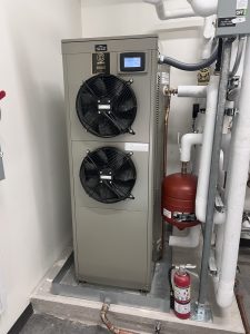
Typical Single Zone Split System

What is a VRF System?

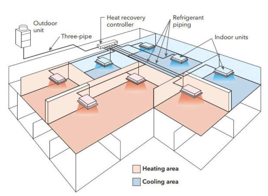
Variable Refrigerant Flow (VRF) systems are a more advanced HVAC technology designed to provide precise temperature control and energy efficiency. VRF systems utilize a single outdoor unit connected to multiple indoor units, allowing for individualized climate control in different areas.

Key Features of VRF Systems:

Quiet Operation: These systems tend to operate more quietly than traditional systems, enhancing indoor comfort.

Energy Efficiency: VRF systems adjust the flow of refrigerant based on each space’s heating and cooling needs, resulting in significant energy savings.

Zoning Flexibility: With the ability to connect multiple indoor units, VRF systems can effectively provide heating and cooling in different zones simultaneously, offering tailored comfort.

Advanced Controls: VRF systems often have sophisticated control options, allowing for remote management and monitoring of each indoor unit.

Typical Multizone VRF System with Simultaneous Heating and Cooling

They Sound Pretty Similar, so What Are the Differences?

1. Design and Configuration

  • Split Systems: Generally simpler, with one outdoor and one or more indoor units. Suitable for smaller installations.
  • VRF Systems: More complex, featuring one outdoor unit connected to multiple indoor units. Ideal for larger spaces or buildings with varying heating and cooling needs.

2. Energy Efficiency

  • Split Systems: While energy-efficient, they don’t offer the same level of modulation as VRF systems, which can lead to higher energy consumption in larger installations.
  • VRF Systems: Highly efficient due to their ability to adjust refrigerant flow based on demand, leading to reduced energy costs over time.

3. Cost

  • Split Systems: Lower initial investment makes them attractive for residential or smaller commercial applications.
  • VRF Systems: Higher upfront cost but often results in lower long-term operational costs due to their efficiency.

4. Installation and Maintenance

  • Split Systems: Easier to install and maintain, requiring less specialized training for technicians.
  • VRF Systems: Installation can be more complex, requiring skilled professionals for proper setup and maintenance.

5. Application Suitability

  • Split Systems: Best suited for single-family homes, small offices, or individual rooms.
  • VRF Systems: Ideal for larger commercial spaces, multi-story buildings, and facilities needing customized climate control.

Conclusion

Choosing between a VRF system and a split system ultimately depends on your specific needs, budget, and the scale of your HVAC requirements. Split systems are excellent for smaller spaces where simplicity and cost-effectiveness are priorities. In contrast, VRF systems shine in larger, more complex environments that demand energy efficiency and precise control. Whether you opt for a split system or a VRF system, both can contribute significantly to your indoor comfort when appropriately selected and installed.

Sustainability Meets a New Era of Learning: Welcome to DPS RASA


New School Year, New School

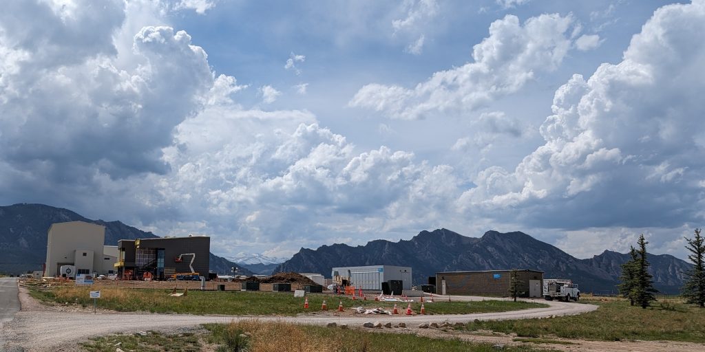
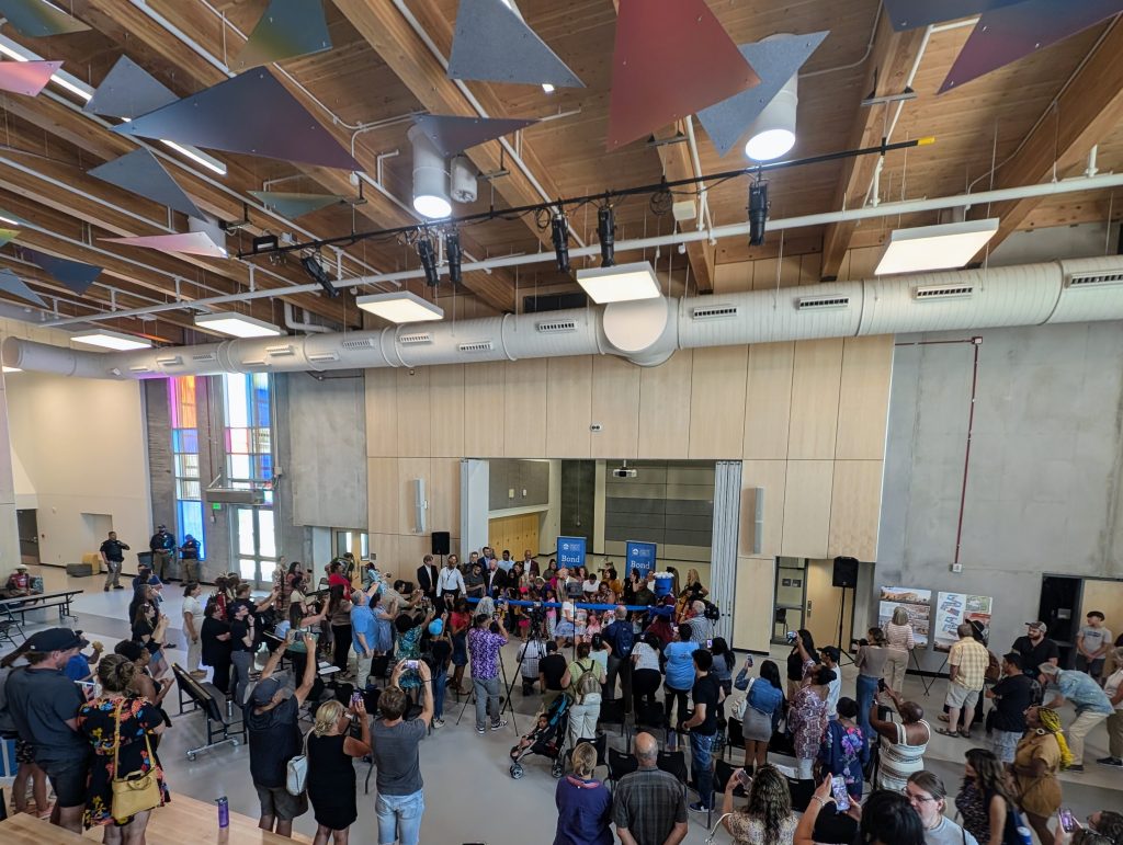
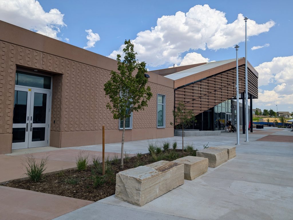
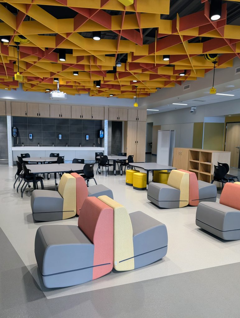
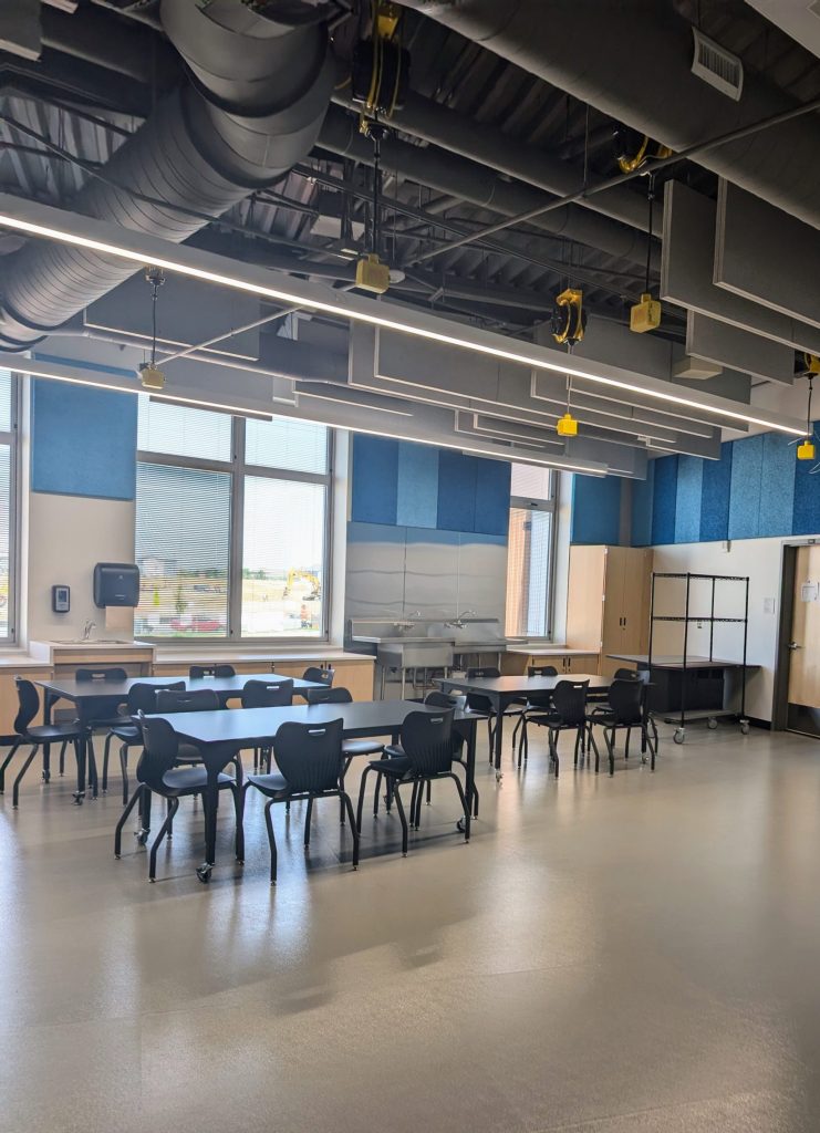
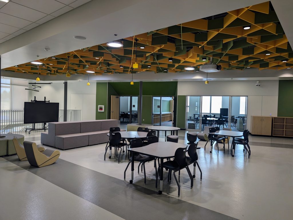
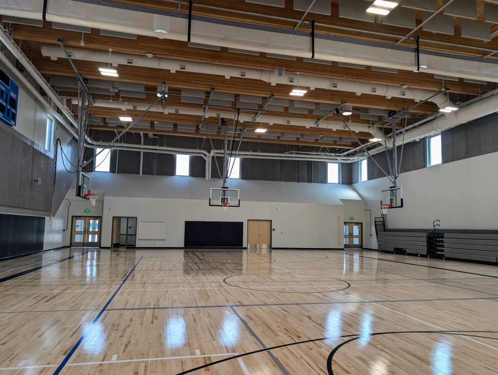
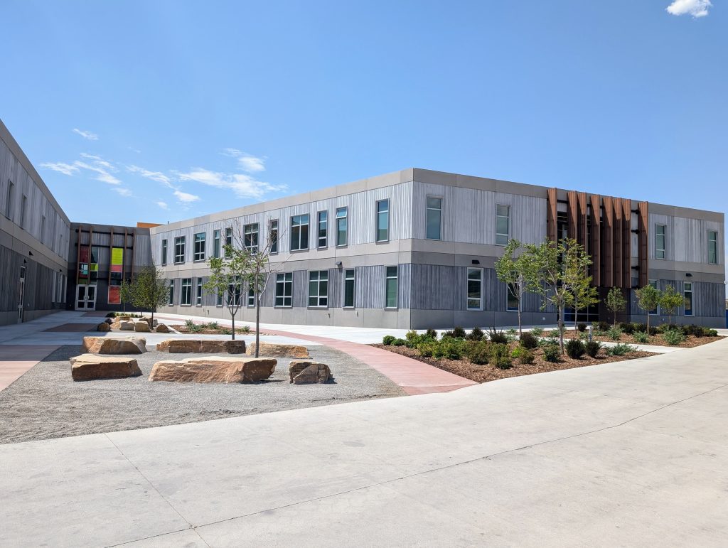
Denver Public Schools (DPS) pushed the design envelope with this over 60,000-square-foot ground-up new school. The current design houses grades ECE through 5th grade with a future Phase 2 expansion to bring it up through 8th grade and just shy of 80,000 square feet. Phase 1 was designed with Phase 2 in mind, from mechanical loads and water heater capacity down to sanitary sewer piping depth. As the architect, DLR Group led the design team in which 360 Engineering provided mechanical and plumbing engineering and consulting. Responsive Arts & STEAM Academy FNE (RASA) hosted its ribbon-cutting ceremony on Friday, August 2, 2024, just in time for the new school year!

The RASA approach is built on a culturally sustaining, community-responsive foundation that respects all learners. It aims to foster a lifelong love of learning through creative and critical thinking, project-based learning, and the discovery of students’ talents. The model emphasizes the Arts as essential to learning, integrating them across subjects to promote higher-order thinking. Historically, students in Far Northeast Denver have lacked access to robust arts education, but RASA seeks to change this by valuing emotional education alongside logic and reasoning, creating a more holistic human experience.

Energy Modeling and Mechanical Systems

The design team was tasked with designing a highly energy-efficient building. Energy modeling was used to compare three mechanical systems:

  1. Packaged Heat Pump Roof Top Units (RTUs) with downstream Variable Air Volume (VAV) boxes with electric zone heating.
  2. A geothermal heat pump system.
  3. Chilled beam cooling with radiant heating flooring.

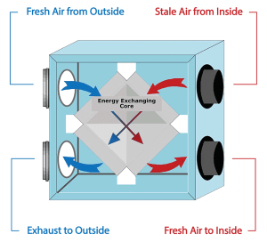
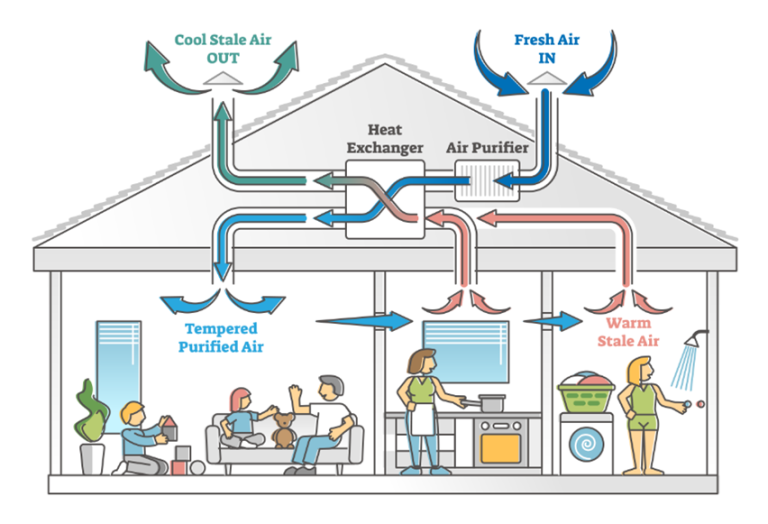
Each system has pros and cons, which were discussed in detail with 360’s input and guidance. The biggest decision points were identified as installation cost, energy efficiency (measured in Energy Use Intensity or EUI, given as a measure of energy use per square foot per year), maintenance requirements, and operational costs. The VAV RTU system was chosen as it provided the best efficiency with the lowest installation cost and a familiar system for the District’s facilities maintenance team to work with. This system also included air-side economizers and energy recovery wheels to further increase efficiency and make use of the dry Colorado air. Additionally, the controls systems monitor CO2 levels in the various spaces and modulate the outdoor air intakes to provide the right amount of ventilation (known as Demand Control Ventilation), providing the right balance between energy savings—less outdoor air to heat or cool—and indoor air quality, keeping CO2 levels down and enough fresh air coming in to keep learning minds active and alert!

All Electric

With RASA’s successful grand opening, the design team immediately began designing the Phase 2 expansion. We are excited to see the school we have designed realize its potential as a safe, energy-efficient facility that will foster growth in the next generation.

With a mindset for the future, the school was designed to be all-electric: the mechanical system is powered using heat pump technology, domestic water heating is electric, and all kitchen appliances are electric—even the ranges and ovens are induction-type! This is the District’s first all-electric school.

Commissioning in the Hottest Place on Earth!


Our projects with the National Park Service take us to some pretty cool places…this is not one of them. Death Valley National Park (DEVA) holds the record for the highest recorded temperature on the face of our planet, at over 130°F! As you might imagine, it takes a lot to keep buildings comfortable in a climate like that. 360 is currently wrapping up a project in DEVA, specifically at Scotty’s Castle, where the design team replaced an outdated water source heat pump system with a full water-cooled chiller plant and hydronic boiler system. The team utilized a former stable building as a mechanical room to house boilers and chillers and routed buried piping hundreds of yards to the castle itself in tunnels built by Scotty nearly 100 years ago. The system utilizes a closed-loop cooling tower to minimize water loss while still taking advantage of the dry air’s low wet bulb temperature to reject heat from inside the castle to the ambient air far away from the building.

Scotty’s Castle, nestled in the hills of Death Valley. The clock tower is not visible from this angle, but it truly adds the castle feel, moat and all!

All in all, a well-thought-out and resilient system that will provide effective and reliable cooling and heating (it does get cold in Death Valley sometimes!) for years to come, making the visitor (and Park staff) experience more enjoyable and sustainable. But the best system design can be crippled if the systems are not properly started up, tested, and deficiencies corrected before the building occupants move in—in other words, commissioning! The certified Commissioning Authorities (CxAs) at both 3601 and AE Design teamed up to visit the site, observe the system installations, and put the equipment through its paces to make sure everything is installed and operating as intended by the design team.

The Stables at Scotty’s Castle are now home to the chillers and boilers that bring 21st-century comfort to the 20th-century castle.

The commissioning process began with a review of the construction documents as well as equipment submittals in order to familiarize ourselves with the systems being installed and the design intent for their function and operation. From there, we developed both pre-functional checklists (PFCs) and functional performance test protocols (FPTs). The PFCs are filled out by the installing contractor and serve as a quality control and assurance check to ensure systems have been provided and built with all necessary components for operation and are ready to be tested against the design intent and sequences of operation. Once the contractor confirms systems are ready for functional testing via the PFCs, the commissioning (Cx) team books a flight and heads to the site for testing.

We check every system visually to confirm that systems and equipment match what was submitted and approved by the design team and that installed layouts match the design intent in the construction documents. We then work with the mechanical and controls contractors to test the systems using the FPT protocols previously developed. These tests include various modes of operation, such as typical occupied/unoccupied operations, generating false heating/cooling loads to make sure the boilers, chillers, various pumps, and valves all react as intended, and even simulating failure modes to make sure that redundant systems come online when needed and equipment is properly protected in the event of a real equipment or system failure in the future. The Cx team documents the installed conditions and the results of the various tests and provides a log of deficiencies to be addressed before final handover of the project to the owner. As needed, the Cx team makes additional site visits to follow up on deficiencies and make sure all systems have been observed as fully operational before issuing the final Commissioning Report.

Commissioning is a vital process, particularly for complex projects and systems. The fact that our team made several trips to the site in order to complete all the testing and re-testing of systems to ensure everything is operating per the design intent and owner’s project requirements illustrates two key concepts. First, that commissioning is critical for the success of a project, as the list of deficiencies and the need for multiple trips to close out those issues clearly shows—rarely is everything installed and operating 100% correctly the first time it’s put to the test! Second, 360 and AE Design are committed to ensuring that the systems turned over to the owner are fully functional and will serve the building occupants well for years to come. It helps that we get to visit some pretty cool places—even if they’re actually rather hot!

The Cx team works with the contractor to manipulate the system controls for various operating conditions and takes verification measurements.

Interested in learning more about Scotty’s Castle? You should be! Check out the links below.2,3

1Wondering how 360 can be the designer and the CxA at the same time? We maintain objectivity by keeping the CxA completely uninvolved with the design team throughout the design process. Our CxAs work for the owner, either contracted directly or under the general contractor and are accountable to only them. While we obviously work together with the design team through the commissioning process, our CxAs always pursue the goal of helping the whole team achieve the owner’s project requirements and are not afraid to challenge the contractor or the design team when needed to attain that goal.

2https://www.nps.gov/deva/learn/historyculture/building-scottys-castle.htm

3https://www.dvconservancy.org/scottys-castle/

Hot Water Decoded: An Introductory Guide to Water Heaters


As the name suggests, water heaters are equipment that will raise water temperature. Water heaters come in many shapes and sizes but can be characterized by storage and energy sources. Storage methods are tank or tankless; the energy source is electricity or fossil fuels. Tank water heaters, also called “storage” type water heaters, hold a set volume of water that is heated through prolonged contact with the internal heating components. Tankless, or “instant,” water heaters use a much higher energy input to heat the water to the desired temperature as it flows to the fixture.

There are two main ways to use electricity to heat water, one being electric resistance and the other by using the electricity to run a heat-pump refrigerant cycle. Electric resistance-style heating elements are simple and have no moving parts, but the energy output is equal to the energy consumed by the coil. Although heat-pump water heaters also use electricity to operate, they “move” heat instead of “creating” it. This process is a more efficient way of heating water, allowing heat pump water heaters to be up to 410% more efficient than an equivalent resistance style.

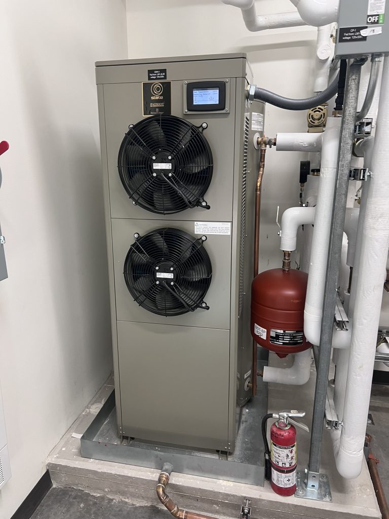
Components of a Heat Pump Water Heater

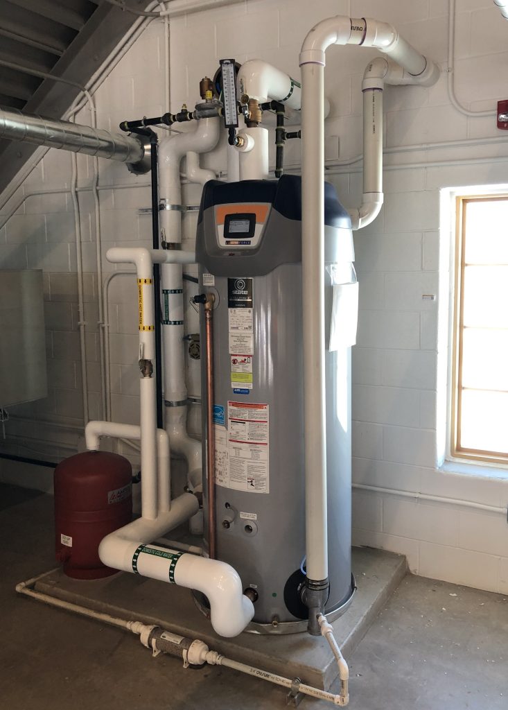
Water heaters that use fossil fuels as the energy source are usually referred to as gas water heaters. The options for source types are most commonly natural gas or propane. Natural gas is the fossil fuel utility most often offered by service providers, while propane is usually shipped and stored in tanks on-site. Although most gas water heaters are similar, the most noticeable difference is between condensing and non-condensing style burners.

When gas-fired equipment burns fuel, it doesn’t use 100% of the energy released from combustion, resulting in a mixture of unburnt fuel and water vapor. If cooled enough, the flue gases can condense on the flue vent piping, leading to corrosion. Hence, manufacturers reserve approximately 20% of the energy released to keep the flue gas temperatures high enough to prevent condensation. More modern gas-fired water heaters will utilize the condensation to put more energy into the water instead of keeping the flue vent gases hot, resulting in efficiencies up to 98%. The corrosive condensate produced by this process is handled by using resilient metals for the heat exchanger and acid-neutralization kits to ensure the condensation produced is safe for sanitary lines and treatment plants.

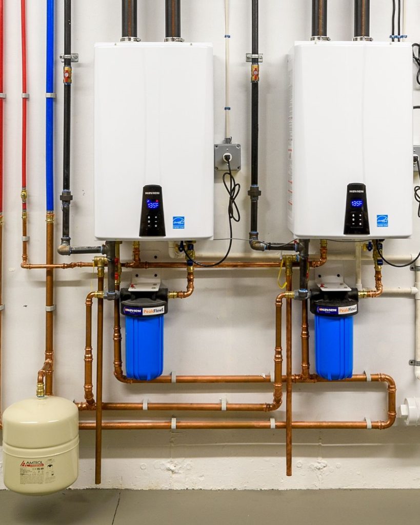
Condensing vs. Non-Condensing Continuous Flow
Tank-Type Water Heaters
Pros
  • Lower instant power consumption to satisfy the hot water demand
  • Fewer components
  • Less expensive to purchase and maintain
Cons
  • Larger footprint
  • Heavy when filled
  • Thermal energy loss over time
  • Less flexible installation options
Tankless Water Heaters
Pros
  • Smaller footprint
  • When sized correctly, provides the user with a constant supply of heated water all year round
  • Less heat loss
Cons
  • Larger energy input
  • Contains more complicated controls and safeties
  • More expensive to purchase
Electric Resistance Water Heaters
Pros
  • Ease of installation (no flues required)
  • Simple/reliable operation
Cons
  • Can require electrical service upsizing
  • Power input depends on voltage availability
Heat Pump Water Heaters
Pros
  • Highest efficiency
  • Provides cooling in the summer by extracting heat from the room
Cons
  • New technology
  • Highest equipment first cost
  • More maintenance
  • Takes energy away from the room, requiring the heating system to compensate in the winter
Gas-Fired Water Heaters
Pros
  • Higher energy density of fossil fuels means smaller pipes are required
  • Provides large volumes of heated water independent from what electrical service is available
Cons
  • Requires combustion air to operate
  • Requires flue vent piping
  • Products of combustion are released near the building, lowering the air quality of the surrounding area

Flowing Forward: Basics in Graywater Recycling and Water Conservation


With climate patterns changing and becoming more unpredictable, water conservation measures are becoming critical to reduce water consumption in our buildings. One way to reduce water consumption and decrease your water utility bill is to utilize a graywater recycling system. Below, we will explore graywater and graywater recycling systems, where they are best to be implemented, and what the requirements are around these systems.

What is Graywater?

Let’s start with the basics. What is graywater? Graywater is nonpotable wastewater from washing machines, showers, bathtubs, lavatories, and HVAC Condensate. It can be treated and recycled for use in water closets/urinals and irrigation systems to reduce your building’s domestic water consumption and wastewater quantity. Graywater is piped separately from the building’s main wastewater system and is routed from the designated fixtures providing graywater to a graywater treatment (if required) and storage system. The exact components of this system will depend on your manufacturer and authority having jurisdiction (AHJ) but it typically consists of a water treatment system, a storage tank, and a pump. The treated graywater will then be routed to the water closets and irrigation systems designed to be served from the graywater systems. Even though the graywater may go through a treatment system, it is important to note that this water is still not potable.

Is a Graywater System Right for Your Building?

Now that we know what a graywater system is, when is a graywater system right for your project/building? To utilize a graywater system to the fullest extent, the project should have a steady and consistent usage of the fixtures supplying the graywater system. Buildings with consistent shower and/or laundry usage provide the best supply to a graywater system. This could apply to hotels, multi-family, fitness/recreation centers, police departments, etc. Buildings without shower or laundry usage can still be a good candidate, but the graywater system may not be capable of providing the water for all the water closets or irrigation needs since the waste from lavatories will typically not equate to the water closet and irrigation usage. A review of the feasibility of a graywater system for a building can be done during the pre-design or schematic design phases with the plumbing engineer and a graywater system manufacturer to determine if it’s a good application for the project.

Requirements

In conjunction with evaluating if a graywater system is suitable for your building based on building type and fixture usage, it will need to be determined that the AHJ allows graywater systems and if they have any special requirements for the system. The City of Denver, for example, allows and encourages graywater systems, but a graywater system installed in the City and County of Denver must meet the requirements of Denver’s Graywater Use Program, which can be found on the city’s website and outlines requirements for graywater systems used for irrigation and toilets/urinals. These requirements include treatment, signage, watercolor, testing, and permitting needs.

Implementation

We have now determined that a graywater system is a good application for our project, and the AHJ allows graywater systems. That great! So, what is next? During the early design phase, the engineer will need to work with the architect and other consultants to ensure the proper location and space are allocated for the system. The graywater system will preferably be located in a room below the fixtures providing graywater so the waste can gravity drain into the treatment/storage system. Ideally, this would be located in a basement. The engineer will also need to determine the required system components based on the application and AHJ to ensure proper space is allocated for the equipment. The system could include treatment equipment, storage tanks, pumps, backflow preventors, valves, etc., so ensuring space is appropriately allocated for this equipment early is critical. If the proper location and space are allocated for the graywater system early, this should set up the design for the remainder of the project.

Overall, a graywater system can be a great way to conserve water usage in your building and decrease water utility costs. Prior to implementing a graywater system in a building’s design, the building’s fixture use should be evaluated for the impact of the graywater system, along with confirming the AHJ requirements for graywater systems to ensure it’s the right approach for the project.

Resources:

The Do’s and Don’ts of Architectural Design: By a Mechanical Engineer


At 360, we love to be team players and share our ideas and insights with our fellow consultants. And boy, do we have ideas! This month, we wanted to help out our architect friends with some brilliant tips and tricks for working with mechanical engineers and making buildings awesome.

Chase Sizes

Everyone loved throwing things down the laundry chute as a kid, so why not bring that excitement to the workplace by adding chases sprinkled throughout the floorplan? Never concede to smaller chases, as they should occupy no less than 25% of the floor. Oh, and make sure you can fit some ductwork and pipes in there if possible. (Picture shown for reference of a building chase)

Do: Provide chases with a minimum of 100 square feet, a large access panel (preferably 3’ wide and 7’ tall with a handle or knob for entry), and a large glass panel to allow observations from outside.

Don’t: Provide only one chase in the building. It may feel entitled and eventually resent the occupants.

Picture shown for reference of a building chase.

Quadruple Paned Windows

Everyone wants to fight for the window seat in the office, but no one wants the perks of afternoon glares, cold spots, and the potential of pedestrians looking in. There are many architectural advances to mitigate those risks, but none more effective than quadruple-paned windows. The more layers you add, the less heat transfers through the window, and the harder someone will have to squint to see inside. While quadruple-paned windows may be a good option, why stop there? Double stacking quadruple pane windows is an even more effective way to not only introduce unique light reflections in the space but also add architectural personality to buildings with windows that are thicker than the walls.

Do: Install double-stacked (heck, even triple-stacked) quadruple-pane windows.

Don’t: Default to the cost-effective, low solar gain, and easy-to-install windows.

Insulation Thickness

Insulation is best described as the warm blanket in the walls that the framing snuggles to keep warm at night. Traditionally, insulation is installed using rigid boards, spray foam, or stuffed batt insulation. However, to give a modern approach to building insulation, we recommend installing rigid dish sponges, silly string spray, or stuffed goose feather pillows as a much better insulation material. If you don’t have any of those materials handy, just stuff the walls with whatever you can find. It’ll be fine!

Do: Provide a wall stuffed full of Kleenex to reduce the HVAC size needed and use the previous batt insulation as blankets on the couch—just be prepared to be extremely itchy as you binge the newest season of Real Housewives.

Don’t: Provide boring rigid or batt insulation in the walls.

Disclaimer: This blog post was released on April 1st, and while 360 Engineering is not a licensed architecture firm, we do have some really great ideas for the advancement of architecture! Call us about your next project; we’ve got quadruple-paned windows ready for you!

COPs Higher than 3’s: The Efficiency of Heat Pumps!


If you’ve been thinking about your mechanical system lately, you’ve probably come across the magical buzzwords “Heat Pumps.” But why does everyone love them so much, and are they really that much better than gas-fired heating equipment?

At its very core, heat pumps just move heat from one space to another, hence the name! At the technical level, they use refrigerant circuits, similar to what’s found in your air conditioner or refrigerator, to extract heat from one space and move it into another. In the ancient, inefficient past, you needed one piece of equipment to heat the space (furnaces, electric heaters, boilers, etc.) and another to cool the space (air conditioners, chillers, etc.) The beauty of a heat pump is that it comes with a small reversing valve within the outdoor unit that can flip the rotation of refrigerant and provide heating instead of cooling to a targeted space. That’s why they’re effective at heating AND cooling the space as a single system.

If all of that has your head spinning, focus on the key terms:

Heat Source: Where is the heat coming from? It could be inside the building, and you want to remove it, or outside it, and you want to bring heat inside.

Heat Sink: Where are you dumping the heat? You can reject heat outside the building to cool the inside spaces down or reject heat inside the building if you want to heat it up.

Coefficient of Performance (COP): This is a ratio of the amount of energy (heat) that comes out of the mechanical system compared to the amount of energy (electricity or fuel) put into the system. Higher is better!

Heat pumps grab heat from the heat source and move it to the heat sink. That’s it! Nothing more complicated about it.

Gas-fired appliances must burn fuel (heat source) to generate heat into the air/water (heat sink), and high-efficiency units have a COP of only ~0.97. Even electric resistance heaters must produce electrical heat to heat the air/water but have an almost equal input-to-output COP of ~1.0. “You get out what you put in.” However, heat pumps don’t rely on heat generation; most of the heat is just transferring already generated heat from one source to another space. And that requires significantly less energy input than generating that heat-so much less energy that the ratio of heat output from a heat pump when compared to the energy it takes to run a heat pump can be upwards of 300% or a COP OF HIGHER THAN 3!

Whether it’s freezing outside or you’re sweating inside your building, heat pumps are an efficient way to relocate that heat to an appropriate heat sink. Gone are the days of accepting a 97% efficient furnace. Now, heat pumps are pushing the limits of energy efficiency, and who can say no to something 3-5 times more efficient than your current boiler?

Here are a few of our current and recent projects where we’ve used heat pumps in the mechanical system design:

  • Arapahoe Library District Administration Building
  • NREL Flatirons Campus Control Center Facility
  • NPS Fort Vancouver National Historic Site Building 725
  • NPS Rocky Mountain National Park Fall River Entrance Station
  • NPS Zion National Park South Campground
  • NPS Tumacacori National Historical Park Satellite Administrative Office Building
  • Denver Zoo Sea Lions Exhibit
  • DPS Fallis Elementary School – READ MORE ABOUT THIS PROJECT

Lovers of Louvers: Mechanical Engineering Romance this Valentine’s Day!


It’s hard to imagine an inanimate object capable of being loved, but let me share my viewpoint.

They matter!  Louvers are used in both intake and exhaust applications for HVAC systems.  Without louvers, we would have large openings on the side of the building with screens, allowing all the snow and rain to enter.  So, how does a louver keep all the driving rain and snow out of the building?  Louvers have varying blade shapes that provide different performances.  All louvers are tested via a standard test to determine the point at which water will pass through.  The air velocity in which water passes through a louver varies anywhere from 300 feet per minute (fpm) to over 1,000 fpm.  When an engineer sizes a louver, they size one such that the velocity of airflow will remain below the tested penetration threshold.  The louver plays an important role in keeping water out of the building.

Louver sizing is also impacted by the amount of free area they provide.  Louvers are rated with pressure drops, which need to be calculated in the sizing of fans within the mechanical system.  A louver that has a high-pressure drop increases the need for a larger fan and more energy usage.  A louver with a low-pressure drop allows for less fan energy.  Who doesn’t love something that takes less energy?

Louvers come in all shapes, sizes, and colors.  They want to be sized to reduce the water penetration and pressure drop, but you can integrate them into the context of the building.  There are rectangular ones, square ones, round ones, triangular ones, and, in the spirit of love, diamond-shaped ones.


When I was a young engineer, spell check was a new tool.  And on one project, all of the keynotes referencing louvers were autocorrected to “lovers.”  The contractor had some fun with this, and I am now on the lookout for “lovers” on projects. 

Denise M. Dihle, PE, 360 Engineering Founder, President, Principal

Cold Climates and Heat Pumps: How It Started, How It’s Going


Electrification and Sustainability Goals: Unveiling the Role of Heat Pumps

As we’ve all continually heard in recent years, electrification is a major sustainability goal for many municipalities, states, and even countries around the world1. Along with electrification comes a plethora of buzzwords and phrases, one of the most familiar being heat pumps. Air-source heat pumps—the most common application due to the relatively low cost of such systems—can absorb heat from the ambient air and transfer that heat into an occupied building space. But how does that work when the outside ambient air is cold?

Air-Source Heat Pumps Demystified: Operation in Cold Climates

Heat pumps manipulate the chemical properties of refrigerants at different pressures to absorb and release heat energy, moving it from outside to inside to heat a building.

At the right pressure, the boiling point of the refrigerant will actually be lower than the cold outside air temperature—and since heat energy always moves from the higher temperature substance (in this case, the outside air) to the lower temperature substance (the refrigerant), heat is absorbed from the “cold” outside air and then cycled to the occupied space.

The Chilling Challenge: How Cold Can Air-Source Heat Pumps Go?

So, heat pumps can pull heat from relatively cold outside air—but how cold can that outside air be?

The short answer is that it depends on the type of heat pump you are working with. Most one-to-one split heat pump systems (i.e., a single outdoor unit connected to a single indoor unit) and packaged heat pump systems (e.g., packaged rooftop units) begin to significantly reduce their heating capacity around 40-45°F ambient temperature—which is when you really start needing the heat!

However, these systems are typically designed to accommodate this derated capacity as the temperature continues to drop. Regardless, one-to-one and packaged heat pump systems are limited in how much heat they can provide at very cold temperatures. Below the “balance point” of derated heat pump capacity and building heating load, supplemental heat becomes necessary, typically in the form of some electric resistance heaters.

Beyond Limits: Variable Refrigerant Flow (VRF) Systems Revolutionizing Cold Climate Heating

The most advanced heat pump technology available today takes the form of Variable Refrigerant Flow (VRF) systems. VRF systems have been around in East Asia and Europe for decades and have gained a foothold in the U.S. in the last 15-20 years. This technology has seen an explosion of progress in that time. A few decades ago, VRF systems were only rated for heating in the range of -5°F to -10°F, below which the systems were configured to shut down to protect their internal components from the “extreme” cold! However, VRF systems today have heating performance data for operation down to -22°F or less! Granted, at a significantly derated heating capacity, but pause and grasp that this technology can pull heat out of -22°F air and move that heat inside your building! The upshot is that the balance point of VRF systems is much lower than the one-to-one or packaged heat pump systems described above. 360 Engineering has designed systems for large buildings in Denver and other cold climates capable of meeting the full heating load at -5°F without any supplemental heat systems required.

Breaking the Cold Barrier: Technological Advances in VRF Systems

Multiple technological advances have allowed VRF to progress to such a viable heating system, even in cold climates. Physical accessories on the outside casing of the heat pump units, such as wind baffles and snow hoods, mitigate the effects of weather on the operation and efficiency of the VRF heat pumps. Inside the heat pumps, flash-injection technology—where the system introduces a modest quantity of mixed-phase refrigerant (i.e., a mixture of gas and liquid) to cool the compressor—allows the compressor to operate at higher speeds by mitigating friction and accumulation of internal heat2. Higher compressor speed results in greater heating capacity for the system at lower ambient temperatures. On top of these technologies in the outdoor unit, VRF systems take advantage of heat recovery internally as well, moving energy from interior zones that have excess heat available to exterior zones that need that heat energy—bypassing the outdoor unit entirely through the use of an intermediate “mode control unit.”

Future Trends: The Journey of Heat Pump Technology in a World Moving Towards Electrification

Heat pump technologies have come a long way since they were first introduced in the HVAC industry. While limitations still exist for certain systems and applications, air-source heat pumps have become a viable and highly efficient option to provide the heat needed for buildings in cold climates. As the world continues toward electrification and the market demands better, higher-performing heat pumps, this technology will continue to progress toward greater heating capacities at colder ambient temperatures.

References

1https://www.forbes.com/sites/energyinnovation/2022/11/15/the-worlds-three-largest-economies-go-all-in-on-heat-pumps-how-policy-can-cut-gas-use-and-energy-bills/?sh=532dbd9c564d

2https://www.achrnews.com/articles/145397-five-things-hvac-contractors-should-know-about-cold-climate-vrf

Gunnison County Library – The Road to Net Zero


Gunnison County Libraries was looking to replace its existing library in Gunnison, Colorado, with a new sustainable building providing flexible and functional community space. The 15,000-square-foot public facility also needed to stand up to the harsh and variable weather conditions experienced in Gunnison. The high-elevation mountain sun is intense all year round, while winter ambient temperatures in the Gunnison Valley can drop below negative 30 degrees. In addition to cold temps, deep and heavy snow is common, so careful design of the roof systems by the Anderson Hallas Architects team was critical to handling snow and ice. 

Energy Modeling and Assistance in Achieving Sustainability Goals

360 Engineering provided mechanical and plumbing engineering services, including energy modeling and assistance in achieving sustainability goals for the project. The design team was tasked with providing a building with an EUI (Energy Use Intensity) under 30.  As a reference, the median EUI for a library in the US is 71.6 (Energy Star Benchmarking).  The energy-efficient mechanical system combined geothermal ground source heat pumps and a variable air volume dedicated outside air system (VAV DOAS) with new DDC controls. The energy model completed at the end of the design predicted an EUI of 27.

Building EUI (Energy Use Intensity) goals for Net Zero

What does a low EUI have to do with Net Zero?  A chart was developed by Building Green (BuildingGreen.com) to provide EUI goals for buildings that, combined with a solar PV array, provide a pathway to a Net Zero building.  The Gunnison Library, a single-story, 15,000-square-foot building, has a targeted EUI of over 50.  However, the chart developed by Building Green is based on a building using 70% electric and 30% natural gas.  Having a goal of reducing fossil fuels and a fully electrified building shifts this chart, and the design goal of under 30 EUI puts us on the right track to achieve Net Zero.

Utilizing Solar

The Gunnison Library utilizes an 18kW solar array with the intent that solar PV could be expanded as the allowable kW per array increases.  The 18kW array provides 1.2 watts per square foot and is a minimal array, considering the average size of residential arrays are 7.1 kW (NREL).  

So, how is the building doing?  Over the last five months, the building has been operating with an EUI of 15.5! As mechanical engineers, this isn’t just a triumph; it’s a testament to our role in shaping a future where Net Zero isn’t a lofty ideal but a measurable reality. It’s a call to action for mechanical engineers everywhere—to engineer not just systems but sustainable solutions that propel us toward a future where our buildings don’t just weather the storm but become beacons of environmental responsibility.